Getting started
The robots are based on the Robotics Shield Kit which is equipped with an Arduino Uno micro-controller. To program this micro-controller you need to install some software on your laptop. Step-by-step instructions for setting up the Arduino software and connecting it to an Arduino Uno:
More information on the Arduino and all hardware components on the robots can be found at the Arduino website. The robotics Shield Kit website from parallax offers another useful introduction into programming the robot.
Programming the robot
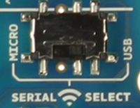
The Wireless SD shield has an on-board switch labelled Serial Select. It determines how the Xbee's serial communication connects to the serial communication between the microcontroller and USB-to-serial chip on the Arduino board.
Put the switch in the Micro position when using the ZigBee communication and put it in the USB position when programming the Arduino.
When in the Micro position, the DOUT pin of the wireless module is connected to the RX pin of the microcontroller; and DIN is connected to TX. The wireless module will then communicate with the microcontroller. Note that the RX and TX pins of the microcontroller are still connected to the TX and RX pins (respectively) of the USB-to-serial converter. Data sent from the microcontroller will be transmitted to the computer via USB as well as being sent wirelessly by the wireless module. The microcontroller will not be programmable via USB in this mode.
With the switch in the USB position, the DOUT pin the wireless module is connected to the RX pin of the USB-to-serial converter, and DIN on the wireless module is connected to the TX pin of the USB-to-serial converter. This means that the module can communicate directly with the computer. The microcontroller on the board will be bypassed. To use the shield in this mode, you must program the microcontroller with an empty sketch (shown below), or remove it from the board.
Hardware components
Detailed information on how to use the various components on the robot can also be found on the Arduino website.
- Ultrasound distance sensor (link)
- Digital encoders (link)
- Gripper kit (link)
- Servos (link)
- ZigBee wireless communication module (link)
I/O pin connections
- Digital 0 - RX ZigBee module
- Digital 1 - TX ZigBee module
- Digital 2 - not used
- Digital 3 (PWM) - not used
- Digital 4 - not used
- Digital 5 (PWM) - not used
- Digital 6 (PWM) - not used
- Digital 7 - left encoder
- Digital 8 - right encoder
- Digital 9 (PWM) - ultrasound sensor
- Digital 10 (PWM) - grabber servo
- Digital 11 (PWM) - ultrasound servo
- Digital 12 - left servo
- Digital 13 - right servo
- Analog 0 - not used
- Analog 1 - not used
- Analog 2 - not used
- Analog 3 - not used
- Analog 4 - not used
- Analog 5 - not used