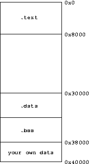
Memory layoutThe following picture shows the memory layout
as known to the LCC compiler. The binary produced by the LCC
compiler follows this layout. That means that at byte 0 there is the
first instruction and at byte 0x30000 there is the first data
element. Note that a data section is only present if you use
predefined arrays or other big data structures in your program. Else
the data section is only used during the program execution. Scalars
are compiled into the text section and loaded using a load immediate
instruction. The bss section is used for dynamically allocated data
and stack. These are normally untouched by the compiler. The data
that resides between the addresses 0x38000 and 0x40000 is not
touched by the compiler. You can put your own data here, the
compiler will never overwrite it.

The mMIPS assumes that we have two memories (mips_rom.bin and
mips_ram.bin) both starting at address 0x0. The content of the
mips_rom.bin is simple to generate. It is symply the start of the
binary produced by LCC. That is why we always use the output of the
LCC compiler as the mips_rom.bin. From the above picture it may seem
that the data memory starts at address 0x2000, while physically it
starts at address 0x0. This issue is resolved by translating every
compiler generated address that start with 0x2000 with a call to the
physical RAM (data memory) and applying a mask to the address. The
relocation is automatically performed by the mMIPS. You don't have
to do anything for it.
Let look at an example of how all of this works. Below you see a
program that realizes a very simple blur filter on an image of 25 by
25 pixels. #define WIDTH 25
#define HEIGHT 25
void main(void)
{
int a, result;
char *buf_i = (char*)0x38000, *buf_o = (char*)0x38271;
for (a=WIDTH+1; a < WIDTH*HEIGHT-(WIDTH+1);a++)
{
result=((
1*(int)buf_i[a-1-WIDTH] +
1*(int)buf_i[a+1-WIDTH] +
4*(int)buf_i[a ] +
1*(int)buf_i[a-1+WIDTH] +
1*(int)buf_i[a+1+WIDTH] +
4) >> 3);
if(result<0) buf_o[a] = 0;
else if (result > 255) buf_o[a] = 255;
else buf_o[a] = result;
}
}
The input image is present at address 0x0 of the data memory and
is accessed through the buf_i pointer. The output image start at
address 0x38271 in the data memory and is accessible through the
buf_o pointer. To use the filter we do the following. First we
compile the program with the LCC compiler. The output binary is
called mips_rom.bin (i.e. it is our instruction memory). We create a
seperate file mips_ram.bin. The first 625 bytes are filled with
pixel values (line-by-line), the rest of the file is left empty. We
den run the mMIPS with our mips_rom.bin and mips_ram.bin. As a
result we have a new mips_ram.dump with the content of the data
memory after executing the program. In this file we find the blurred
image data starting at byte 626.
|