
Synchronous Dataflow
SDFG-based MP-SoC design flow
| Tool | sdf3flow-sdf |
|---|---|
| API | class SDF3Flow |
The number of applications integrated into new consumer electronics devices is increasing rapidly. At the same time, user expectations on the quality of these devices is ever increasing. To manage the design complexity, a predictable system and design flow are needed that guarantee that an application can perform its own tasks within strict timing deadlines independent of other applications running on the system. This requires that the timing behavior of the hardware, the software, as well as their interaction can be predicted.
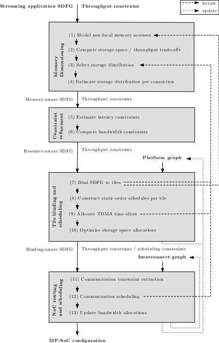
SDF3 combines a large number of modeling, resource allocation, analysis and scheduling techniques into a coherent design flow that maps a streaming application onto a NoC-based MP-SoC architecture while offering a predictable timing behavior. The objective is to minimize the resource usage while offering guarantees on the throughput of an application when mapped to the system. The design flow is shown in in the figure below. It takes as an input a throughput-constrained, streaming application that is modeled as an SDFG. This streaming application SDFG is mapped in 4 phases onto a NoC-based MP-SoC architecture. The first phase of the design flow, called memory dimensioning, deals with the storage-space that is needed for the tokens communicated over the edges of the SDFG. When a token does not fit into the local memory of a processing tile, it transforms the streaming application SDFG to model accesses to this token when it is stored in a memory tile. The memory dimensioning phase computes also the trade-off space between the storage-space allocated to the edges of the graph and the maximal throughput that can be realized under those allocations. It uses this trade-off space to constrain the storage space of the edges in the application SDFG. The next phase, called constraint refinement, uses these storage constraints to compute latency and bandwidth constraints on the edges of the graph. All these constraints are used to steer the binding of actors to the tiles of the MP-SoC architecture. This binding process is performed in the third phase of the design flow. This phase, called tile binding and scheduling, constructs also a static-order schedule for the actors of an application that are bound to the same tile. Furthermore, it allocates TDMA time slices on all tiles and it tries to minimize the storage-space allocations. The final phase of the design flow, the NoC routing and scheduling phase, deals with the allocation of TDMA slots on the links of the NoC. This starts with the extraction of the NoC scheduling problem from the binding and scheduling decisions made in the previous phase of the flow, after which a solution is searched for the NoC scheduling problem. Finally, the actual bandwidth usage of the NoC schedule is computed. This information is used to update the amount of resources that is available for the next application that should be mapped to the same NoC-based MP-SoC architecture. At various steps of the design flow, the used algorithms may not be able to find a solution which satisfies the resource and/or timing constraints. In those situations, an iteration over (part of) the design flow must be made. The possible iterations are shown with dashed lines in the figure. Iterations occur due to the lack of resources (step 7) or infeasible timing constraints (step 9 and 12). In those situations, the design flow iterates back to the first or third step of the flow and design decisions made in those steps are revised. When going back to step 1, more or different tokens should be placed in a memory that is accessed over the NoC. Reverting back to step 3 implies that the storage space allocated to the edges is too constrained for meeting the throughput constraint. So, a different storage distribution should be chosen. More information on the design flow can be found in "Predictable Mapping of Streaming Applications on Multiprocessors".
The NoC-based MP-SoC design flow has also been implemented in SDF3. To use the NoC-based MP-SoC design flow, a user must input a streaming application SDFG and a NoC-based architecture, both described in XML format, into SDF3. The tool will automatically perform most of the steps in the design flow. Iterations to previous steps of the flow are also performed when needed. The only step that requires manual intervention is the first step of the design flow. In this step, the user must manually insert the SDF memory access model for the appropriate actors and specify the properties of the newly added actors and edges. At every step of the flow, the complete state of the design flow can be outputted in XML. The user can then manipulate the design decisions made by the flow and continue the flow on a next step. The tool also allows a user to by-pass part of the flow and replace this part with his own custom algorithms.
When using the command-line tool sdf3generate-flow, the settings of the design flow are specified in a settings file. An example of such a file is shown below.
<?xml version='1.0' encoding='UTF-8'?>
<sdf3 type='sdf' version='1.0'
    xmlns:xsi='http://www.w3.org/2001/XMLSchema-instance'
    xsi:noNamespaceSchemaLocation='http://www.es.ele.tue.nl/sdf3/xsd/sdf3-sdf.xsd'>
  <settings type='flow'>
    <applicationGraph file='app.xml'/>
    <architectureGraph file='arch.xml'/>
    <tileMapping algo='loadbalance'>
      <constants>
        <constant name='a' value='1.0'/> <!-- processing -->
        <constant name='b' value='0.0'/> <!-- memory -->
        <constant name='f' value='0.0'/> <!-- communication -->
        <constant name='g' value='0.0'/> <!-- latency -->
      </constants>
    </tileMapping>
    <nocMapping algo='greedy'>
      <constraints>
          <maxDetour d='10'/>
          <maxNrRipups n='10'/>
          <maxNrTries n='0'/>
      </constraints>
    </nocMapping>
  </settings>
</sdf3>
A description of the XML format that is used in the settings file can be found in the SDF3 XML file format reference guide.